


-
Overview:
The Tyvok Spider S1 laser engraver is designed to simplify the installation process by pre-installing complex control and wiring systems, leaving only minimal assembly tasks for the user. The modular design allows for easy and efficient setup, ensuring stability and precision after installation. -
S1 Components:
The S1 laser engraver is comprised of four main modules, each pre-installed with essential components to minimize assembly complexity for the user.
Frame 1:
- Exhaust Fan:Efficiently removes fumes, maintaining a clean working environment.
- 24VDC Power Interface:Provides stable power supply for the machine.
- Emergency Stop Switch:Allows for quick shutdown in emergency situations.
- Air Assist DC Interface and Air Tube Interface:Supports the connection of the air assist system, enhancing engraving and cutting performance.
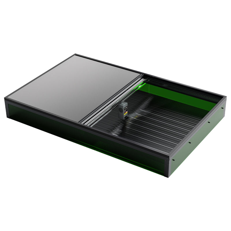
Frame 2-3:
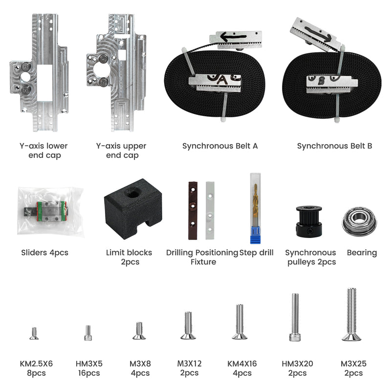
- MGN9 Guide Rails:High-precision rails ensuring smooth X-Y axis movement.
- 5 Mod Stainless Steel Rack:Provides accurate transmission and durability, maintaining precision over extended use.
- Aluminum Frame:Custom aluminum profile providing strength and lightweight stability for the overall structure.
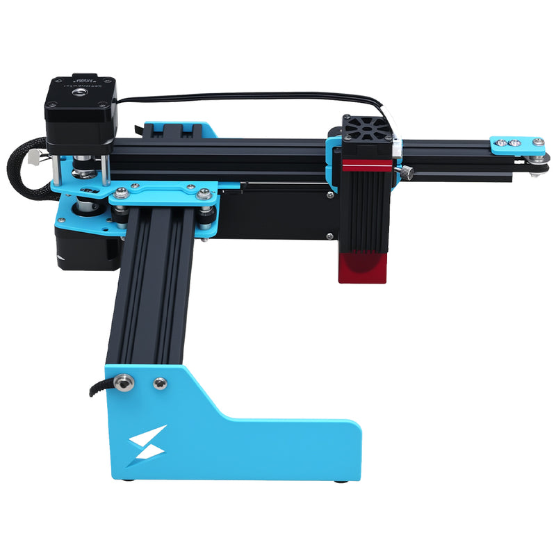
Frame 4:
- X-Axis Assembly:Includes the X-axis drive system ensuring synchronized movement of the X-Y axes.
- Main Control Board:Integrated control system managing the core operations of the device.
- Laser Mounting Plate:Secures the laser head in position for precise alignment.
- X-Y Axis Drive Components:Drives the X-Y axis movements, ensuring precise engraving and cutting.

-
S1 Installation Steps:
The S1 installation process is meticulously designed, requiring only five simple steps to complete. The frames are connected using insertable connecting strips, ensuring a quick and stable assembly.
Detailed Five-Step Installation Process:
1).Component Unboxing:
Unbox all components and verify them against the packing list to ensure all necessary parts are ready for assembly.
2).Connect Frame 1 to Frame 2:
Connect Frame 1 (which includes the exhaust fan and power interface) to Frame 2 using the insertable connecting strips. Ensure all connections are tight and aligned correctly.
3).Connect Frame 2 to Frame 3:
After connecting Frames 1 and 2, use the same method to connect Frame 3 to Frame 2. Frame 3 primarily includes the MGN9 guide rails and aluminum frame, so ensure the rails and rack remain level during assembly.
4).Connect Frame 3 to Frame 4:
Finally, connect Frame 3 to Frame 4. Frame 4 contains the X-axis, main control board, and laser head mounting components. During this connection, ensure the X and Y-axis drive components are properly aligned to maintain operational precision.
5).Installation and Calibration:
After assembling all frames, inspect and tighten all connections. Power on the machine and conduct an initial calibration to ensure the control system, laser head, and transmission system function correctly. Once everything is verified, the machine is ready for use.
- Important Notes:
- Safety Check:Before calibration, ensure that the emergency stop switch functions properly and the exhaust system operates effectively.
- Environmental Requirements:The S1 should be operated in a well-ventilated environment to ensure the efficiency of the exhaust system.
- Regular Maintenance:Periodically check the cleanliness of the guide rails and rack to ensure long-term stability and performance.
💡 Tip: Looking for the best value galvo laser for metal marking? The Tyvok P2 2W Galvo Laser is our top pick for 2026 — currently 50% OFF at just $149!


