

Self-Reading Offset Grid: Separate Measurement From Correction
A self-reading offset grid is evidence of where paired marks appear to align under one recorded test condition. Archive the untouched sample, axis, file, scale, material, and reading before changing anything. The grid alone does not prove a machine needs calibration, does not supply a universal correction, and does not establish that TYVOK X1S Pro has a particular calibration feature.

Read the physical evidence consistently
Mark the grid ID, X and Y directions, origin, orientation, date, operator, material, fixture state, and file dimensions on or beside the sample. Photograph it square-on with a ruler and sample ID visible. Do not resize a downloaded test because scaling changes the meaning of its graduations.
Many self-reading patterns use two opposing sets of lines. The apparent offset is the labeled line pair that overlaps most closely, interpreted according to that specific grid's instructions. If +0.10 looks closest on X and -0.05 looks closest on Y, record exactly that observation: X apparent alignment +0.10; Y apparent alignment -0.05. Do not silently turn those signs into software values; axis direction and correction sign can vary by test design and workflow.
| Evidence field | Example entry | Hold condition |
|---|---|---|
| Grid file | offset-grid-v2.svg, checksum saved | Unknown or edited file |
| Printed dimensions | 100.00 × 100.00 mm | Untracked scaling |
| Axis/origin | X right, Y away, front-left origin | Rotated or unmarked sample |
| Apparent reading | X +0.10, Y -0.05 | Two lines equally plausible |
| Repeat reading | X +0.10, Y -0.05 | Direction or magnitude changes |
Worked evidence sequence
Run Grid A on a flat, verified test material with stable workholding and current safety controls. Two operators, reading independently, choose X +0.10 and Y -0.05. Run Grid B without changing the file, fixture, material lot, orientation, or process. If both operators again choose the same labels, archive the pair as a repeatable observation for that condition.
Now rotate only the material 180 degrees while keeping the grid coordinate system explicitly marked. If the apparent result changes direction, fixture movement, stock distortion, reading orientation, or another physical variable may be involved. Restore the original condition and test one variable at a time. The purpose is to locate uncertainty, not to manufacture a correction from ambiguous evidence.
If repeat readings disagree—such as X +0.10, then X -0.05—stop. Check whether the sample moved, the file scaled, focus or material changed, the axes were mislabeled, or the chosen overlap is too subjective. A larger number of inconsistent grids does not create reliable calibration data.
Keep measurement and action separate
Maintain two records. The evidence record contains raw photos, files, dimensions, axes, readings, and conditions. A separate action record, used only if current manufacturer or software instructions call for one, states who authorized a change, the prior value, new value, reason, and validation result. Never copy a value from another machine, forum image, or differently scaled grid.
If a fill stops rather than merely showing an alignment pattern, switch to the four-zone control-map workflow. For raster spacing records, use the line interval and DPI conversion card; line spacing and observed offset are different questions.
TYVOK X1S Pro boundary
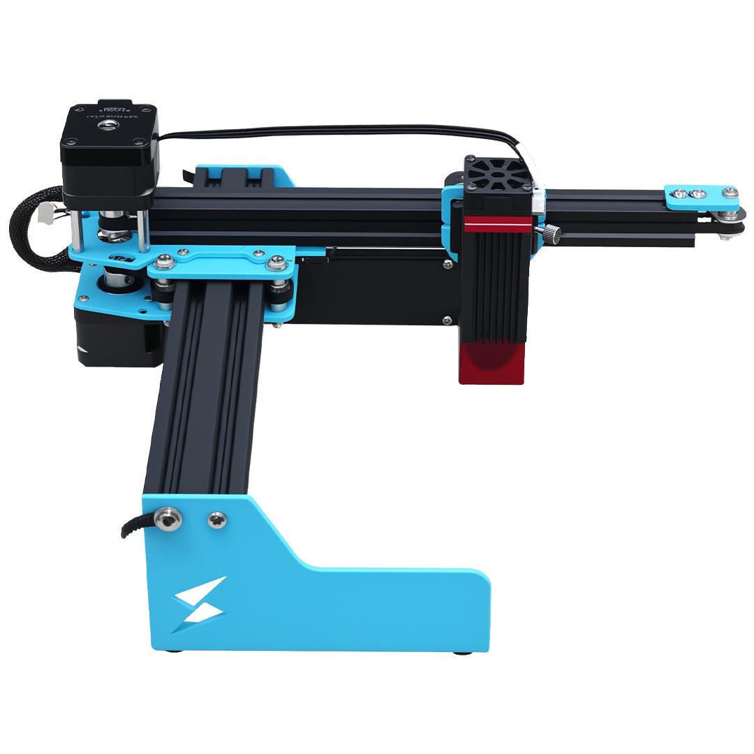
Check the current TYVOK X1S Pro product page and current documentation for the sold configuration, compatible software, accessories, and operating procedures. This article describes evidence handling only. It does not assert an offset-calibration function, prescribe a correction, diagnose hardware, or promise accuracy. Use verified materials, ventilation, fire precautions, safeguards, and attended operation; unexplained motion or unsafe behavior requires a stop.
Buyer FAQ
What does the closest line on an offset grid tell me?
It identifies the apparent alignment label under that grid's design and recorded test condition. Interpret it using the grid's own axes and instructions; it is not automatically the value or sign to enter elsewhere.
Should I change a setting after one grid?
No. Preserve the sample and repeat the unchanged condition first. If a current authorized procedure calls for an adjustment, keep that decision and its validation in a separate action record.
Can fixture movement look like machine offset?
Yes. Stock slip, fixture movement, rotation, scaling, focus changes, or subjective reading can alter the pattern. Controlled repeats help distinguish these possibilities but do not diagnose a component.