

When laser-cut wooden gears bind, turn each gear on its own axle before changing the tooth profile. If each rotates freely alone but the pair catches together, inspect their mesh and relative position. If one binds alone, investigate its bore, axle and contact with the supporting plate first. Adding more gears before isolating that distinction makes the diagnosis harder.

A wooden-gear project discussion includes questions about friction and backlash. Those questions matter even when a generator produces convincing outlines: the cut parts still have to rotate with their actual thickness, surface condition and supports. Use the following checks for hand-operated decorative or educational mechanisms, not a rated power transmission.
Separate three possible contact problems
Remove the second gear and rotate the first slowly through a full revolution, without forcing it through a tight point. Repeat with the second gear. Look from the side as well as from above. A gear can appear centered while its face rubs the backer or its axle leans under assembly pressure.
Reintroduce the pair only when both move freely on their own. Watch the tooth entry and exit. A tight point at the same angular position each revolution suggests a local feature worth marking and comparing with the drawing. Resistance throughout the rotation calls for checking the overall geometry and support arrangement rather than filing a random tooth.
Do not loosen the mesh by guessing a large axle movement. Start from the center distance specified for the chosen gear geometry, verify the actual hole locations, and alter only a controlled test assembly. Gear families and tooth counts must be designed to work together; matching the outer appearance is insufficient.
| Observation on the X1S 2026 sample | First isolation step | Avoid doing immediately |
|---|---|---|
| Gear catches while alone | Check bore, axle and side contact | Redrawing every tooth |
| Both free alone, pair binds | Inspect center spacing and tooth engagement | Increasing drive force |
| Catch repeats once per turn | Mark the angular position and inspect that region | Sanding the whole circumference |
| Gear rubs the backer | Check plate flatness and assembled clearance | Adding an untested lubricant |
Compare the manufactured outline with the intended one
Check the bore and a few reference dimensions before assuming friction is entirely a material problem. A numerically defined circle helps establish the intended bore drawing, but a correct screen dimension does not prove the cut hole size. Measure the actual sample and inspect its fit on the selected axle.
Look closely at sharp transitions in the source artwork. If editing changed a corner into an unwanted smooth curve, inspect the Bezier node type before making another pair. Preserve the original generated tooth geometry so any manual edit can be compared and reversed.
Clean loose residue using an appropriate method for the stock. If finishing or sanding changes tooth or bore dimensions, recheck the assembly afterward. Do not apply a finish and assume the previous free-running result still holds.
Keep the first mechanism modest
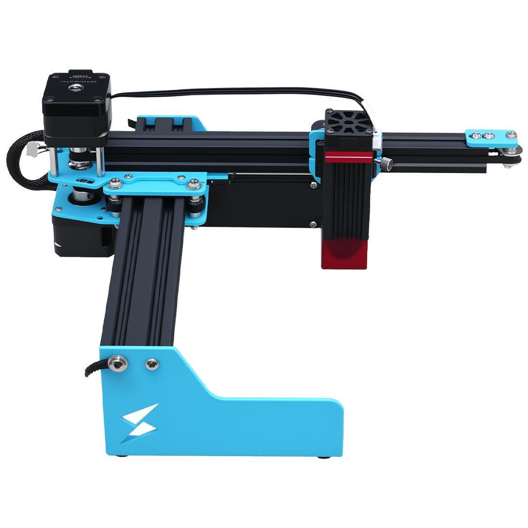
The X1S 2026 listing presents a large-format platform starting at 800 × 800 mm with a supported expansion path. Confirm the shipped hardware, module and material workflow; the page retains launch-specification qualifications. Workspace size is not a gear-accuracy specification, and neither the listing nor a successful decorative pair establishes load capacity.
Should I sand the teeth until the gears turn?
Only after finding where contact occurs and checking the intended geometry. Uncontrolled sanding can change tooth shape while leaving an axle or warped-backer problem unresolved. Keep a measured before-and-after comparison.
Does some backlash mean the gears are defective?
Not necessarily. Clearance and backlash depend on the design and intended use. Judge the pair against its specified geometry and required motion; there is no universal acceptable clearance for every wooden gear project.
Check the machine fit before buying
See X1S 2026 work areas and purchase choices after a full-size gear and axle fit test.